


intro
Much robotics research in recent years has been devoted to the subject of odometry. Knowing a robot’s precise location in the world is key for navigation and obstacle detection and avoidance. Currently a number of methods are used, including wheel odometry, GPS, and SLAM systems, but each of these has flaws in its current implementation. Because wheel odometry is inherently an indirect measurement, it is only valid for short periods of time and fails completely if the vehicle is running on sand or another similarly deformable material. GPS is prone to outages and failures in canyons and under bridges and has an exponential price-accuracy relationship. SLAM performed on external landmarks is processing-intensive because of the feature-recognition and matching necessary.
By using an optical mouse chip to track the ground directly beneath the vehicle, we can overcome these obstacles. Since we are measuring ground-truth, wheel slip does not create any errors so we can theoretically track on sand or track the velocity of a vehicle that is drifting around a corner. Since there are no satellites involved, outages will only be caused by optical obstructions of the ground and monolithic optical mouse IC’s are remarkably inexpensive for their capabilities. Though optical flow is a subset of SLAM, the processing is done in hardware in the optical mouse IC, so performance is unrelated to the interfacing microprocessor.
This is not to say, though, that using an optical mouse IC does not come with its own problems. A standard optical mouse is designed to work in contact with the surface it is measuring and can only read up to 40in/s, making it worthless for all but the simplest of robots. I have overcome both of these obstacles and created a simple and compact packaging for the optical mouse IC that makes it extremely useful to large mobile robots as a ground-truth velocimeter.
Hardware
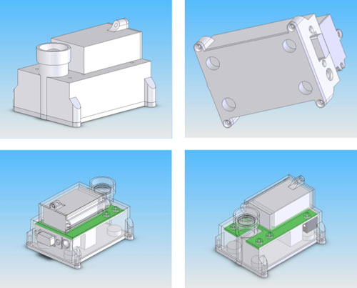
The hardware design for this system focused on the requirements of being securely mounted on the underbelly of a car. To function underneath a car, the system must be able to attach to the curvy stamped sheet-metal forms and be water and dirt resistant enough to avoid damage due to the dirt and rocks kicked up by the wheels. This necessitated an enclosed design to protect the electronics and a shield for the lens to avoid scratching and other damage.
To attach to the car, I decided to use four 5862K65 (Ultra-High-Pull Neodymium Disc Magnet 3/8" Dia, 1/4" Thick, 4.7 Pull lbs, Nickel Plated) magnets from McMaster-Carr, one in each corner. This allows the system to be attached anywhere underneath the car without having to worry about mounting bolts or fasteners.
The power for the system comes from an integral 9V battery that externally plugs into the board for easy connection/disconnection. The battery is included inside the case to provide shielding for it, as well.
Optics
The optics are very important as they scale the velocity and surface features so that the optical mouse can function. The system uses an Edmund Optics NT46-660 aspherical condenser lens (15mm x 12mm) in addition to the standard optical mouse lens included with the ADNS-3080.
We can calculate the magnification of the system so that we can convert the velocity measured by the ADNS-3080 into the real velocity of the road:
$$M = {d_{image}}/{d_{object}} = h_{image}/h_{object}$$
The size of one count of the ADNS-3080 on the optical plane is .0025in. Converting this to the road plane:
$${1.2cm}/h_{road} = {1ct @ pf}/{1ct @ rd}$$ $$1ct @ rd = h_{road}/1.2 * 1ct @ pf$$
This equation gives us a factor by which to scale the ‘counts’ per second coming out of the system to a ‘road cm’ per second which gives us the absolute velocity of the vehicle in both X and Y.
Electronics
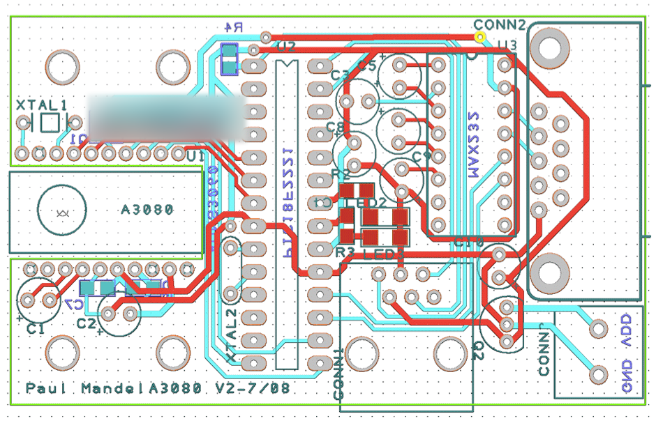
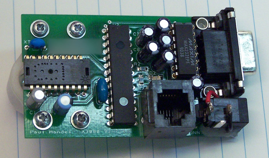
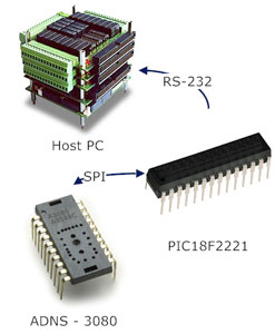
This system is based around the Avago ADNS-3080 High-performance Optical Mouse Sensor. It is Avago’s highest performance model, designed for high-end gaming mice, and can detect motion up to 40in/s and 15g acceleration at 6400 frames per second at 400cpi resolution. It has a non-standard 20-pin offset DIP which makes it difficult to prototype with as a custom breakout board is required in all cases. It communicates over a 3-line (MISO, MOSI, SCLK) SPI serial port that is easily accessible through an interfacing microcontroller and supports simple registry read/write operations and a burst mode that is useful for streaming large amounts of data quickly.
A Microchip PIC18F2221 microcontroller acts as the interface between the computer and the ADNS-3080. The PIC family of microcontrollers is a standard low-cost embedded option for simplistic applications. They include hardware modules for various standard functions such as timing, serial communication, digital input and output, and D/A conversion.
The final IC in the system is the MAXIM MAX232, a TTL to RS-232 level shifter. The TTL signals output by the PIC’s USART range from +5V to 0V, whereas the RS-232 standard requires signals of +12V to -12V. The MAX232 uses charge pumps to make up this gap and requires several large external capacitors.
I custom-designed the PCB you see in the picture above and sent it out to have it built. I did all the assembly myself.

Software
There are three main components to the software architecture used in the system.
The ADNS-3080 has a very low level interface using a synchronous serial port and direct registry reading and writing. It also supports a special ‘streaming’ mode of communication for transmitting or receiving large amounts of specially-formatted data. For more information on the communication protocol used by the ADNS-3080, please reference the ADNS-3080 datasheet online.
The PIC18f2221 is from a standard family of microcontrollers (PIC18) produced by Microchip. It is programmed in-circuit in C using a special IDE and compiler distributed free to students. It is equipped with many digital I/O ports, a hardware EUSART (asynchronous to communicate over RS-232), and a hardware MSSP (synchronous to communicate via SPI). All of these ports are easily set up and accessed via function calls in the code.
The program I wrote for the PIC is designed to serve as a direct pass-through connection to the ADNS-3080, with a few exceptions. This means that if you send ‘0x00 0xFF’ (read from register zero and return the result) over the serial port, you get back ‘0x00 0x17’, which is the product ID, the default value of that registry (and a good way to check if communication is working all up and down the line). The cases where this breaks down are for the streaming modes. The PIC intercepts a write to either 0x40 or 0x50 and takes control of the process:
- 0x50
- To grab a frame, the PIC needs to download 900 uint8’s from the ADNS-3080. Unfortunately, the PIC doesn’t have enough room in its onboard memory to accommodate all that data, so it returns 9 strings of 100 uint8’s each. When using this mode, set up the a binary read to take in 100 uint8’s 9 times so your serial connection doesn’t time out. You should only really use this to adjust the focus and make sure there’s proper illumination because the frame rate is only around 1hz.
- 0x40
- Instead of grabbing the motion data as is, the PIC erases the motion data, waits a variable amount of time, and then returns the amount of time it waited and the x and y motion data, effectively giving a very precise and scalable velocity reading. It returns exactly those 3 uint8’s, so you should configure your serial read command appropriately.
The host PC, in this case the computer in the back of the vehicle, runs some version of Matlab to work with the computer’s serial port. To interface the ADNS-3080 breakout with XPC, I created a mask in Simulink that handles all the serial communication and just spits out the time-compensated x and y velocities, updating at 15hz. This greatly simplifies interaction with the ADNS-3080 breakout for most users. Any users wishing to use the pass-through functionality described above are advised to use a custom m-script run through regular Matlab.